Er diagram online services
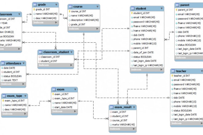
An ER diagram is a type of flowchart that shows how entities, typically people, objects or concepts, are related to each other within a system. ER diagrams are most often used in business to design relational databases. In computer science, they are used to design ontologies.
An entity relationship diagram (ERD) is a graphical representation of the relationships between entities in a database. An ERD can be used to represent the data in a database, as well as the relationships between the data.
There are many online services that can help you create an ER diagram. Some of these services are free, while others require a subscription. If you need help creating an ER diagram, consider using one of these online services.
Top services about Er diagram online
I will be your virtual assistant to help and save time
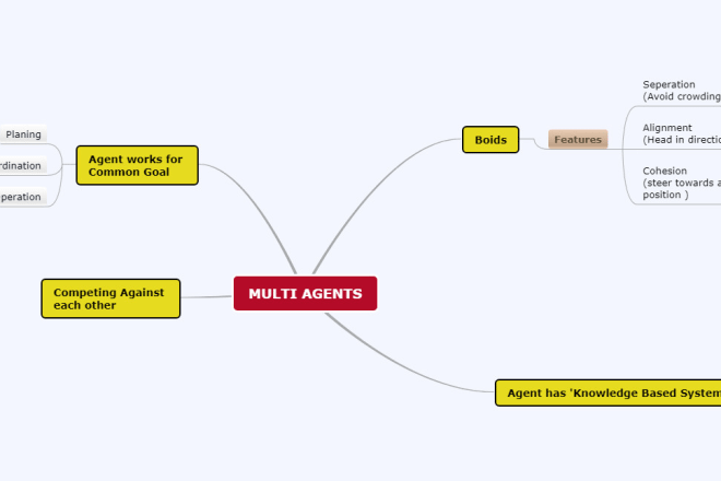
I will help you in theory advance software engineering tasks
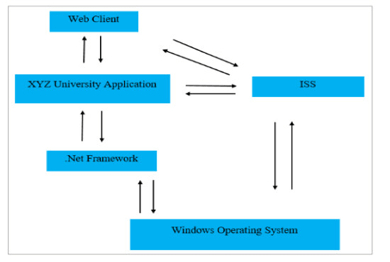
I will draw your diagrams according to your tasks
I will develop online database web base application system

I will design and create database, create er diagram,write sql queries to satisfaction
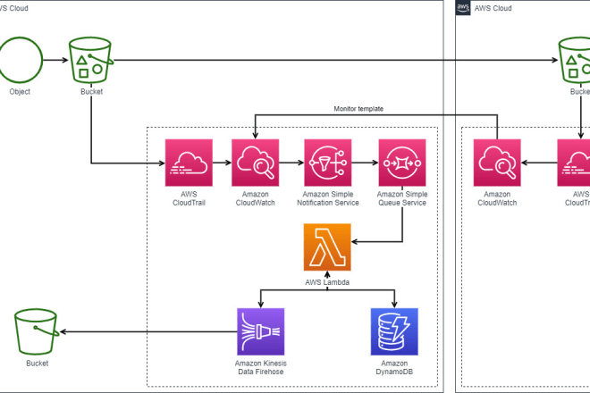
I will design infoghraphics, flow diagram, flow chart for AWS architecture
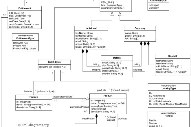
I will create any uml diagram, erd and dfd for you
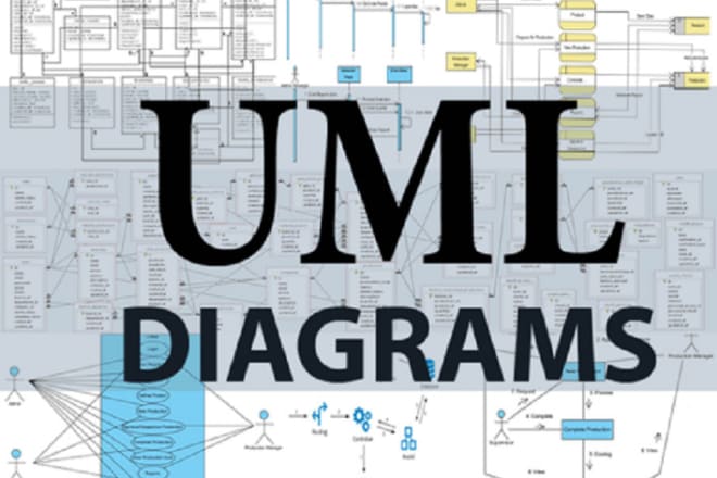
I will do professional uml,erd, class and sequence diagrams
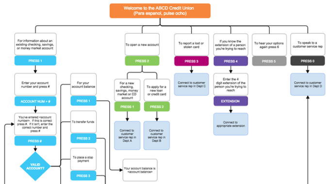
I will draw flow diagram,uml diagram,network diagram,business diagram etc in visio
- Title infographic flowchart or diagram
- Recommendation colors
- Picture you want in VISIO
I can design:
- Infographic flowchart
- Flow Charts
- Activity Diagram
- UML diagram
- Network Diagram
- Organizational Charts
- Business Diagrams.
- Process Flowchart.
- Cross Functional Flowchart.
- Data Flow Diagram.
- Workflow Diagram.
- Website Designing Flow diagram.
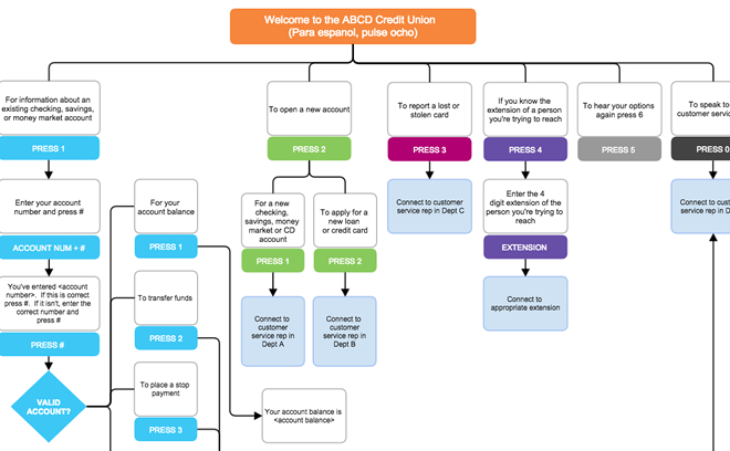
I will draw flow diagram,uml diagram,network diagram,business diagram etc in visio

I will make uml diagram, class, state chart, network, activity diagram in 1 hour
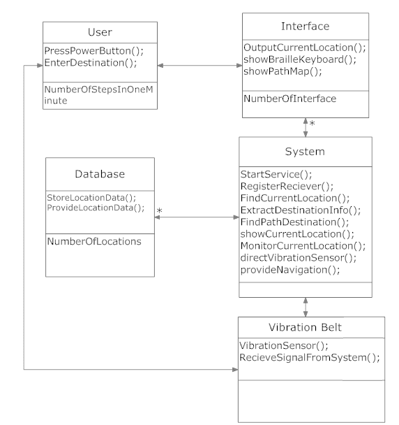
I will do uml desgining for You
i can alsp make charts , bar diagram , graphs and ER Diagram for your databases.
i can guarantee you would love my service .
feel free to Contact me :)
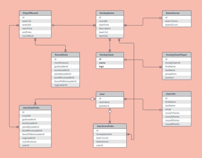
I will design er diagram and db diagram for your requirements
1) Optimization
2) Normalize up to 3rd normal form
3) Industrial best practice
4) Deliver with DB scripts
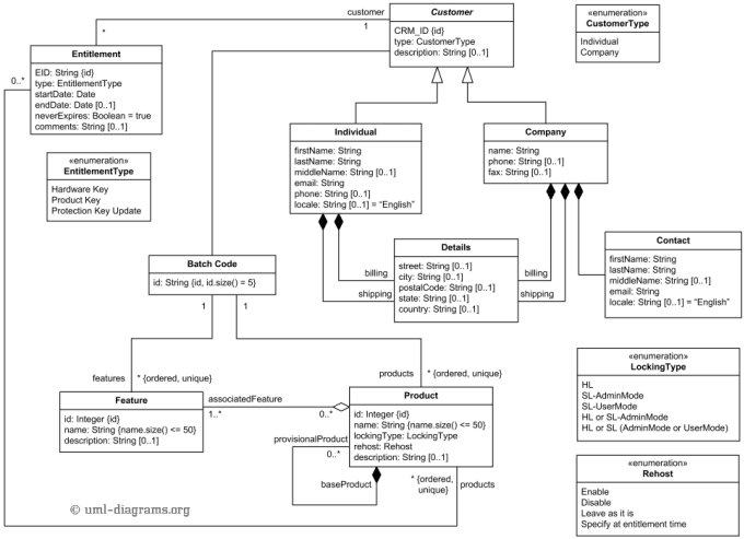
I will do all on system analysis and design, uml modelling
I will help to do all tasks on System Analysis and
Design, UML Data Modelling, that including:
1. Use Case Diagram
1.1 Use Case to XML
2. Sequence Diagram
3. Class Diagram
4. Object Diagram
5. Component Diagram
6. Deployment Diagram
7. Interaction Diagram
8. State Diagram
9 Activity Diagram
Special on:
1. Data Flow Diagram (DFD)
1.1 Context Diagram
1.2 Level 0 Diagram, Level 1 Diagram
1.3 Structure English
1.4 Data Dictionary
2. Control Flow Graph (CFG)
3. Dominant
Tree
Service is provided with BEST QUALITY and ASAP.
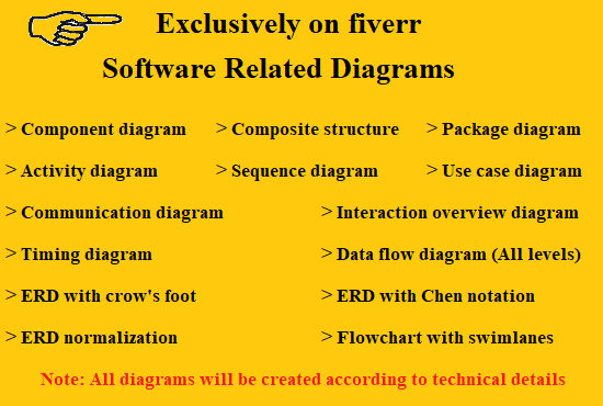
I will create flow chart uml use case and other diagrams
[Contact Me Before Ordering]
Are you looking for help for your software ( project ) design Diagrams? Then your search is over. I can provide the help you in following:
- Class diagram
- Package diagram
- Object diagram
- Component diagram
- Composite structure diagram
- Deployment diagram
- Activity diagram
- Sequence diagram
- Use case diagram
- State diagram
- Communication diagram
- Interaction overview diagram
- Timing diagram
- Flowchart with swim lanes
- ERD with Chen Notation
- ERD with Crow Foot Notation
- ERD Normalization
- Data Flow Diagrams (All Levels)
Note: All the scenarios based diagrams will be created according to provided instructions.
I can also help you in the Full project according to the scenario. but please remember price may vary.
Contact Me If Something is not listed
