Er diagram uml services
An entity relationship diagram (ERD) is a graphical representation of an information system that shows the relationships between entities in that system. In an ERD, entities are represented by rectangles, and relationships are represented by lines between the rectangles. An ERD can be used to represent a system at any level of detail, from the high-level overview that shows only the major entities and relationships, to the low-level details that show all the attributes of each entity. In a UML diagram, services are represented by rectangles with rounded corners. The name of the service is written inside the rectangle, and the operations that make up the service are listed inside the rectangle. A service can have any number of operations, and an operation can be part of more than one service. In an information system, a service is a group of operations that are performed by a software component in order to provide a specific function to the system. For example, in a word processor, the service of opening a document would be made up of the operations of reading the file from the disk, parsing the file, and initializing the document data structures. Services are usually defined by a service contract, which specifies the interface to the service and the conditions under which the service can be used.
ER diagrams are a type of UML diagram that is used to model the data in a database. They are often used to design or reverse engineer databases. Services is a term that can refer to any type of work that is performed for a customer or client.
In conclusion, an ER diagram is a powerful tool for modeling the data in a system, and can be used to generate UML diagrams for services. However, it is important to understand the limitations of ER diagrams and how they can be improved.
Top services about Er diagram uml
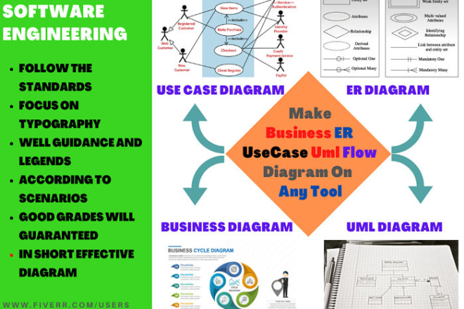
I will make business, er, usecase uml, flow diagram on require tool
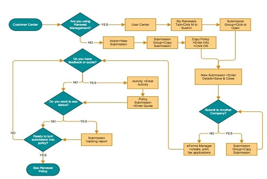
I will make effective process flow diagrams, layouts in visio
I will make uml,class, er,use case,flow diagrams for your projects
I will do database design, sql queries,uml,er diagram for mysql,oracle and ms access
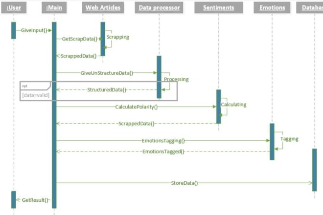
I will make your all uml diagrams
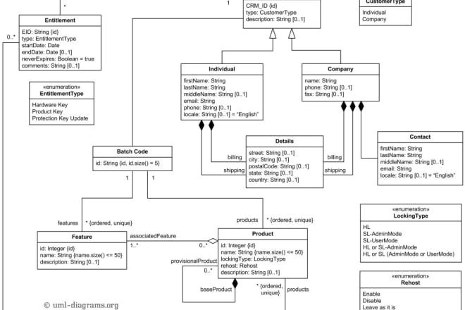
I will create any uml diagram, erd and dfd for you
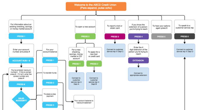
I will draw flow diagram,uml diagram,network diagram,business diagram etc in visio
- Title infographic flowchart or diagram
- Recommendation colors
- Picture you want in VISIO
I can design:
- Infographic flowchart
- Flow Charts
- Activity Diagram
- UML diagram
- Network Diagram
- Organizational Charts
- Business Diagrams.
- Process Flowchart.
- Cross Functional Flowchart.
- Data Flow Diagram.
- Workflow Diagram.
- Website Designing Flow diagram.
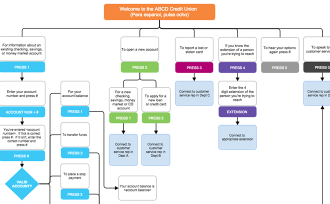
I will draw flow diagram,uml diagram,network diagram,business diagram etc in visio

I will make uml diagram, class, state chart, network, activity diagram in 1 hour
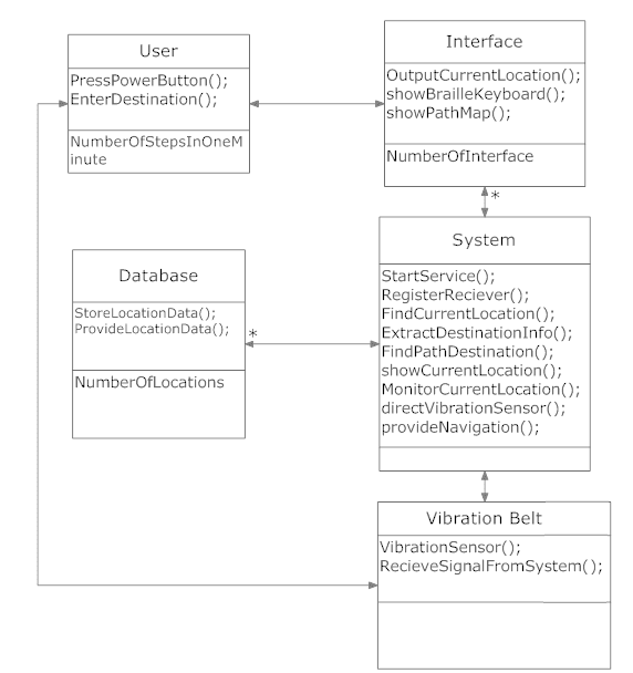
I will do uml desgining for You
i can alsp make charts , bar diagram , graphs and ER Diagram for your databases.
i can guarantee you would love my service .
feel free to Contact me :)
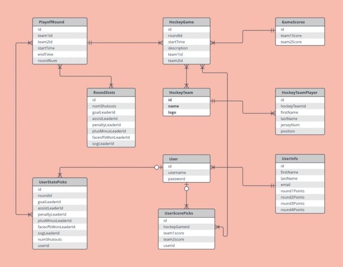
I will design er diagram and db diagram for your requirements
1) Optimization
2) Normalize up to 3rd normal form
3) Industrial best practice
4) Deliver with DB scripts
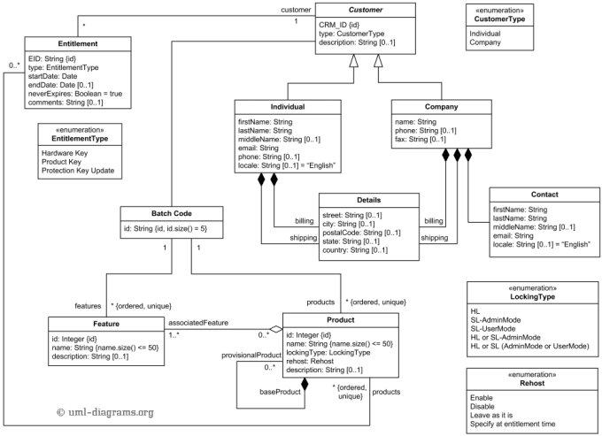
I will do all on system analysis and design, uml modelling
I will help to do all tasks on System Analysis and
Design, UML Data Modelling, that including:
1. Use Case Diagram
1.1 Use Case to XML
2. Sequence Diagram
3. Class Diagram
4. Object Diagram
5. Component Diagram
6. Deployment Diagram
7. Interaction Diagram
8. State Diagram
9 Activity Diagram
Special on:
1. Data Flow Diagram (DFD)
1.1 Context Diagram
1.2 Level 0 Diagram, Level 1 Diagram
1.3 Structure English
1.4 Data Dictionary
2. Control Flow Graph (CFG)
3. Dominant
Tree
Service is provided with BEST QUALITY and ASAP.
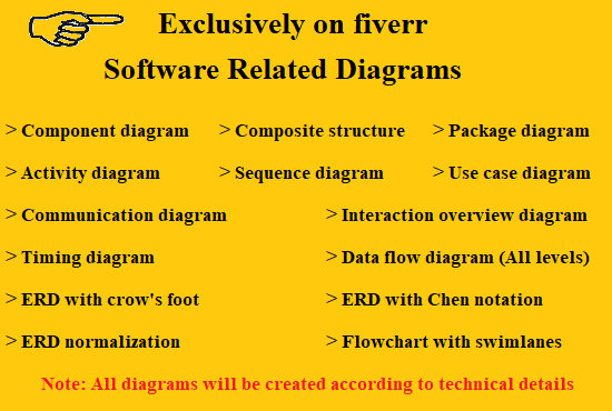
I will create flow chart uml use case and other diagrams
[Contact Me Before Ordering]
Are you looking for help for your software ( project ) design Diagrams? Then your search is over. I can provide the help you in following:
- Class diagram
- Package diagram
- Object diagram
- Component diagram
- Composite structure diagram
- Deployment diagram
- Activity diagram
- Sequence diagram
- Use case diagram
- State diagram
- Communication diagram
- Interaction overview diagram
- Timing diagram
- Flowchart with swim lanes
- ERD with Chen Notation
- ERD with Crow Foot Notation
- ERD Normalization
- Data Flow Diagrams (All Levels)
Note: All the scenarios based diagrams will be created according to provided instructions.
I can also help you in the Full project according to the scenario. but please remember price may vary.
Contact Me If Something is not listed

I will design uml class, erd, usecase and all diagrams in 24hr

I will make uml, use case, data flow, activity or sequence diagrams
I will make ERD diagram UML Diagram of the any given data. I can create following
⚑ Activity Diagram
⚑ Flow Chart
⚑ Class Diagram
⚑ Sequence Diagram
⚑ Use Case Diagram
⚑ State Chart Diagram
⚑ Data Flow Diagram
I can also fix errors and mistakes in your diagrams & will provide you in different formats of your choice like .docx or .pdf or jpeg or HTML with possibly less time.
Please contact before placing the order.