Networking topology diagrams services
A network topology diagram is a schematic representation of a network, showing how the various components of the network are interconnected. Topology diagrams can be used to represent both physical and logical networks. Physical topology diagrams show the actual physical layout of the network, while logical topology diagrams show the logical relationships between the various components of the network. Topology diagrams are an important tool for network administrators, as they can provide a quick and easy way to see how the network is configured. They can also be used to troubleshoot network problems, as they can help to identify where the problem lies. There are a variety of different types of topology diagrams, and the most appropriate type of diagram will depend on the purpose for which it is being used. Some of the most common types of topology diagrams include: - physical topology diagrams - logical topology diagrams - star topology diagrams - bus topology diagrams - ring topology diagrams - mesh topology diagrams
A networking topology diagram is a graphical representation of a computer network. It shows the relationships between the various elements of the network, including the devices, the computer systems, the software, and the data.
The article concludes by discussing the different types of networking topologies diagrams available and how they can be used to better understand the relationships between networked devices. By understanding the capabilities and limitations of each type of diagram, network administrators can more effectively design and troubleshoot their networks.
Top services about Networking topology diagrams

I will design packet tracer labs and microsoft visio diagrams
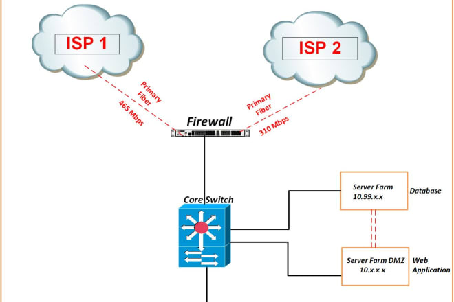
I will design network topology diagrams, flow charts in ms visio
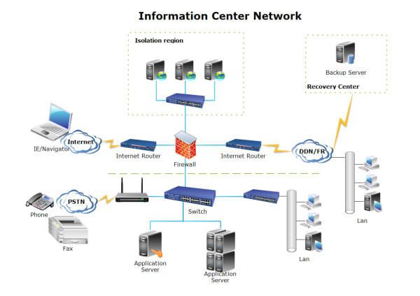
I will design a network diagram for sme companies
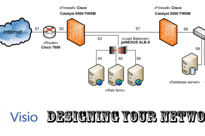
I will design your network diagrams using microsoft visio
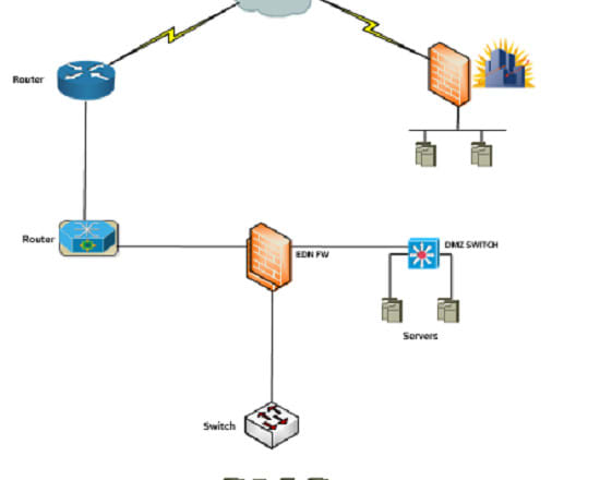
I will design network topology on ms visio

I will design your network diagrams topology flow charts using visio
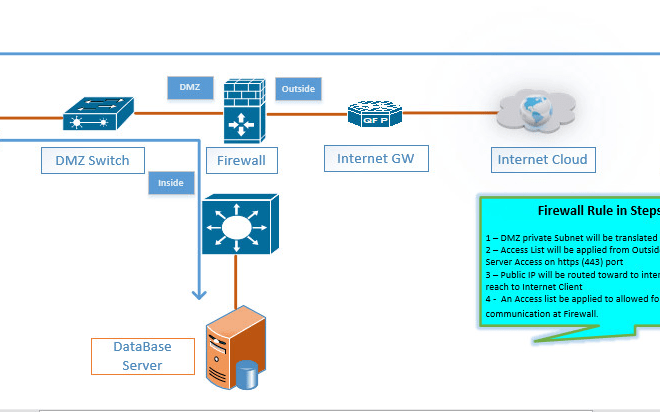
I will design network topology diagrams in microsoft visio in a day

I will design visio network topology flow diagram in 24 hours
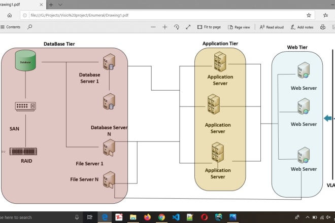
I will create software engineering visio uml models
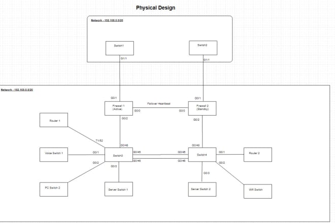
I will create a detailed network topology diagram

I will help in network projects and cisco networking design
Main features:
1) solving Network issue
2) designing of Network Topology
3) Configuration of Cisco devices
4) Assignment of Network
5) Configuration of TP Link devices
and So on...

I will design creative visio network topology flow diagram
I will do networking project and assignment
I am an Engineer in CSE (Computer Science and Engineering) and also network Engineer certified from CCNA / CCNP. I have deep knowledge in networking filed. I will help your network related project or assignments. I can design and configuration any LAN, MAN Network in Cisco packet tracer or GNS3 and other network design simulators.
I can help you:
- fixing any networking issues
- Configuration of Cisco devise
- Create any network topology
- Network Design
- Networking Labs
- Remote Access
- LAN,MAN and WAN
- Firewall configuration
- IPv6
thank you very much for reading my Gig, please do not hesitate to message me if you have any further question.
Kindest regards
Mozammal Hosen
I will make proper topology of your characters for animation
